Specifications
Copyright © Quectel Wireless Solutions Co., Ltd. 2026. All rights reserved.
Specification parameters
Quectel Pi H1 |
Description |
|---|---|
Package |
PCBA |
Dimensions (mm) |
(108 +0.10/-0.15) × (68.70 +0.10/-0.15) × (20.77 +0.10/-0.15) |
Weight (g) |
68 ±0.5 |
Key parameters
Category |
Description |
|---|---|
Application processor |
High-performance 64-bit octa-core processor, delivering up to 12 TOPS of computing power 1 × A78 @ 2.7 GHz + 3 × A78 @ 2.4 GHz + 4 × A55 @ 1.9 GHz32 KB L1I cache, 32KB L1D cache and 512 KB L2 cache |
GPU |
Adreno™ 643L @ 812 MHz |
Memory |
8 GB LPDDR4X + 128 GB UFS |
Operating system |
Yocto Linux (Kernel 5.15)* / Debian 13* |
Weight (g) |
Approximately 67.6 |
USB interfaces |
1 × USB 3.1 Type-C , compatible with USB 2.0. with up to 5 Gbps data rate 2 × standard USB 2.0 Type-A , supporting host mode only,and with up to 480 Mbps data rate 1 × USB Type-C for main power supply |
Display interfaces |
1 × USB Type-C (DP over USB Type-C), DisplayPort 1.4, with up to 4K (3840 × 2160) @ 60 fps1 × Micro HDMI ①, Micro HDMI 2.0 (Frame rate to be determined*). decoding: 4K (H.264/ H.265/ VP9) @ 30 fps1 × FPC connector ①, 4-lane MIPI DSI D-PHY 1.2, 1280 × 800 @ 60 fps |
Audio interfaces |
1 x 3.5 mm CTIA/AHJ (U.S.) & OMTP (China) combo audio jack 1 × micro HDMI for audio output*1 × on-board DMIC1 × speaker |
Camera interfaces |
2 × FPC connectors, 4-lane MIPI CSI, with up to 2.5 Gbps/ lane data rate |
Ethernet interface |
1 × standard RJ45 , supports 10/100/1000 Mbps Ethernet |
PCIe interface |
1 × FPC connector, 1-lane PCIe 3.0. with up to 8 GT/s ×1 lane data rate |
SD card interface ② |
1 × SD 3.0, 4-bit SDIO |
UART interface |
1 × DBG_UART ,only for debugging |
ADC interfaces |
3 × ADC header pins (max. input voltage: 1.8 V) |
Expansion interfaces |
6 × I2Cs (multiplexed with other interfaces)1 × I2S (multiplexed with other interfaces)4 × SPIs (multiplexed with other interfaces)4 × UARTs (multiplexed with other interfaces)3 × PWMs (multiplexed with other interfaces)28 × GPIOs (multiplexed with other interfaces)1 × SDIO ② (switchable) |
Key interfaces |
1 × PWRKEY,for turn-on/ turn-off; internally pulled up 1 × KEY1, user-definable function button 1 × KEY2, user-definable function button 1 × USB_BOOT, a function button that forces the product into download mode |
LED indicators |
Red, blue and green |
Antenna interfaces |
1 × Wi-Fi / Bluetooth antenna connector1 × RF coaxial connector (ECT818000500), compatible with ECT818003008 RF coaxial cable③ |
WLAN |
2.4 GHz & 5 GHzIEEE 802.11a/b/g/n/ac |
Bluetooth |
5.0④ |
Temperature ranges |
Operating temperature: -20 °C ~ +70 °C Storage temperature: -40 °C ~ +85 °C |
Power supply requirements |
USB Type-C power input, which must be a PD-compatible adapter capable of 9V/3A or 5V/5A output |
Shielding cover |
N/A |
Firmware upgrade |
USB0OTA* |
RoHS |
All components are fully compliant with the EU RoHS Directive 2011/65/EU |
Notes:
*:Under development.
①:The Micro HDMI interface and MIPI display interface are mutually exclusive and cannot be used simultaneously.
②:The SD card functionality is switch-selectable between an on-board card slot and a 2 × 20-pin SDIO header, which are mutually exclusive and cannot be used simultaneously.
③:The product offers two configurable antenna solutions. For details, please contact Quectel Technical Support.
④:The product is fully compliant with all mandatory Bluetooth 5.0 features but does not implement optional features such as the 2 Mbps BLE PHY or Advertising Extensions.
Functional block diagram
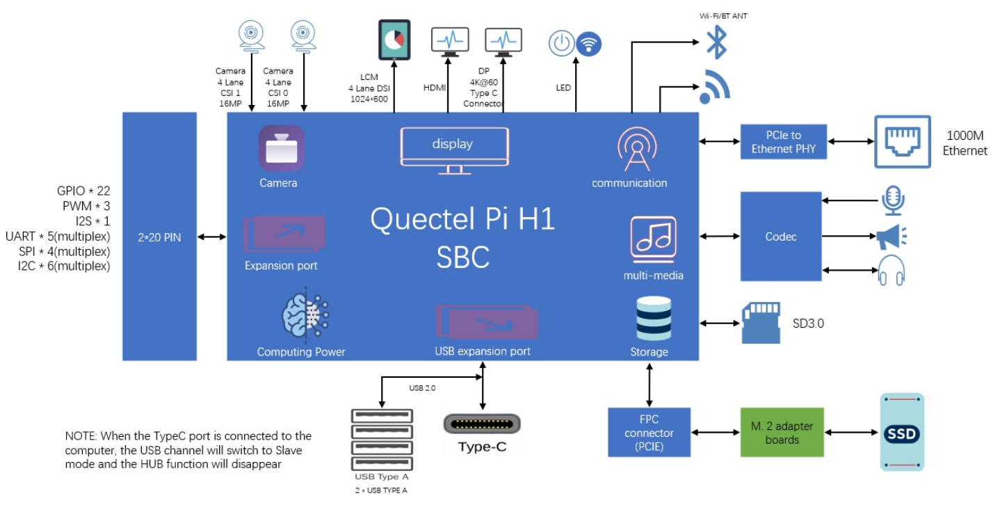
Interface description
Detailed interface diagram
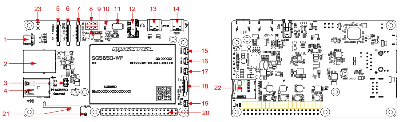
Interface description table
No. |
Interface name |
Description |
|---|---|---|
1 |
Micro HDMI |
Micro HDMI video output interface, supports 4k @ 60 Hz |
2 |
Ethernet |
Supports 10/100/1000 Mbps Ethernet |
3 |
Fan connector |
5V fan power connector |
4 |
USB Type-A |
2 standard USB 2.0 Type-A interfaces |
5, 6 |
Camera interface |
2 channels of 4-lane MIPI CSI, the maximum data rate is 2.5 Gbps/ lane |
7 |
DSI display interface |
1 channel of 4-lane MIPI DSI D-PHY 1.2, 1280 × 800 @ 60 fps, the maximum data rate is 2.5 Gbps/lane |
8 |
UART |
Debugs UART, for debugging only |
9 |
ADC |
3 channels of ADC test interface pins, maximum input voltage 1.8 V |
10 |
DMIC |
Digital microphone |
11 |
Speaker |
Speaker output, 2-pin 1.25 mm pitch universal speaker connector |
12 |
Headphone |
3.5 mm audio interface, audio output |
13 |
USB Type-C |
Display interface: USB Type-C interface (DP Over USB Type-C), DisplayPort 1.4, maximum 4K (3840 × 2160) @ 60 fpsexpansion interface: USB 3.1 Type-C interface, compatible with USB 2.0 |
14 |
USB Type-C power supply |
DC power input via USB Type-C; supports PD protocol |
15 |
PWRKEY button |
Power on/off button, need to long press this button to power on when the “auto power-on” function is not enabled |
16 |
KEY1 |
User-definable function |
17 |
KEY2 |
User-definable function |
18 |
PCIe |
PCIe 3.0 interface for high-speed peripherals, the maximum data rate is 8 Gbps |
19 |
USB_BOOT |
Forces the product to enter download mode |
20 |
2 × 20-pin header |
Multi-function GPIO header; multiplexed with I2C, SPI, PWM, etc. |
21 |
Wi-Fi/Bluetooth PCB on-board antennaRF Coaxial connector |
Wi-Fi/Bluetooth PCB on-board antenna or RF coaxial connector ECT818000500 |
22 |
SD card |
Push-type SD card slot, compliant with SD 3.0 protocol |
23 |
Auto power-on switch |
Switch for “auto power-on” function when powered |
Two antenna options are available: Wi-Fi/Bluetooth PCB on-board antenna or RF coaxial connector. When the PCB on-board antenna is selected, the RF coaxial connector will not be soldered on the product.
40-Pin connector definition
The following is the pin definition list for the 2 × 20-pin connector:
Pin No. |
Pin name |
Pin No. |
Pin name |
|---|---|---|---|
1 |
3V3 |
2 |
5V |
3 |
I2C0_SDA |
4 |
5V |
5 |
I2C0_SCL |
6 |
GND |
7 |
GPIO_77 |
8 |
UART_TXD |
9 |
GND |
10 |
UART_RXD |
11 |
GPIO_16 |
12 |
GPIO_101 |
13 |
GPIO_17 |
14 |
GND |
15 |
GPIO_18 |
16 |
GPIO_32 |
17 |
3V3 |
18 |
GPIO_33 |
19 |
SPI_MOSI |
20 |
GND |
21 |
SPI_MISO |
22 |
GPIO_19 |
23 |
SPI_CLK |
24 |
SPI_CE0 |
25 |
GND |
26 |
SPI_CE1 |
27 |
I2C1_SDA |
28 |
I2C1_SCL |
29 |
GPIO_49 |
30 |
GND |
31 |
GPIO_48 |
32 |
GPIO_76 |
33 |
GPIO_78 |
34 |
GND |
35 |
GPIO_103 |
36 |
GPIO_34 |
37 |
GPIO_35 |
38 |
GPIO_104 |
39 |
GND |
40 |
GPIO_102 |
Camera pin definition
The following is the pin definition list for the Camera 1 22-pin connector:
Pin No. |
Pin name |
Pin No. |
Pin name |
|---|---|---|---|
1 |
GND |
2 |
MIPI_CSI0_LN0N |
3 |
MIPI_CSI0_LN0P |
4 |
GND |
5 |
MIPI_CSI0_LN1N |
6 |
MIPI_CSI0_LN1P |
7 |
GND |
8 |
MIPI_CSI0_CLKN |
9 |
MIPI_CSI0_CLKP |
10 |
GND |
11 |
MIPI_CSI0_LN2N |
12 |
MIPI_CSI0_LN2P |
13 |
GND |
14 |
MIPI_CSI0_LN3N |
15 |
MIPI_CSI0_LN3P |
16 |
GND |
17 |
CAM_GPIO20_L |
18 |
GPIO133&MCLK_L |
19 |
GND |
20 |
CAM_I2C_SCL0_0 |
21 |
CAM_I2C_SDA0_0 |
22 |
VDD_3V3_CAM1 |
The following is the pin definition list for the Camera 2 22-pin connector:
Pin No. |
Pin name |
Pin No. |
Pin name |
|---|---|---|---|
1 |
GND |
2 |
MIPI_CSI1_LN0N |
3 |
MIPI_CSI1_LN0P |
4 |
GND |
5 |
MIPI_CSI1_LN1N |
6 |
MIPI_CSI1_LN1P |
7 |
GND |
8 |
MIPI_CSI1_CLKN |
9 |
MIPI_CSI1_CLKP |
10 |
GND |
11 |
MIPI_CSI1_LN2N |
12 |
MIPI_CSI1_LN2P |
13 |
GND |
14 |
MIPI_CSI1_LN3N |
15 |
MIPI_CSI1_LN3P |
16 |
GND |
17 |
CAM_GPIO21_L |
18 |
GPIO45&MCLK_L |
19 |
GND |
20 |
CAM_I2C_SCL1_0 |
21 |
CAM_I2C_SDA1_0 |
22 |
VDD_3V3_CAM2 |
PCIe pin definition
The following is the pin definition list for the PCIe 16-pin connector:
Pin No. |
Pin name |
|---|---|
1 |
PCIE1_RST_N |
2 |
PCIE1_CLK_REQ_N |
3 |
PCIE1_WAKE_N |
4 |
PCIE1_PWR_EN |
5 |
GND |
6 |
PCIE1_TX0_M |
7 |
PCIE1_TX0_P |
8 |
GND |
9 |
PCIE1_RX0_M |
10 |
PCIE1_RX0_P |
11 |
GND |
12 |
PCIE1_REFCLK_M |
13 |
PCIE1_REFCLK_P |
14 |
GND |
15 |
VCC_5V |
16 |
VCC_5V |
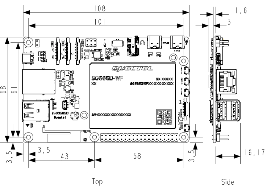
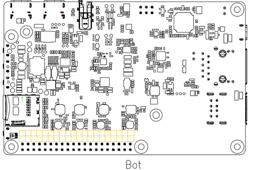
Mechanical dimensions
This section describes the mechanical dimensions of the product, all dimensions are in mm. For all dimensions without marked tolerances, the tolerance is +0.10/-0.15.
Electrical characteristics
Absolute maximum ratings
Parameter |
Minimum |
Maximum |
Unit |
|---|---|---|---|
USB Type-C supply voltage |
-0.3 |
20 |
V |
Digital pin voltage of expansion interface |
-0.3 |
3.6 |
V |
Note: Exceeding the operating conditions shown in the above table may cause permanent damage to the product.
Power supply ratings
The product can be powered through the POWER IN Type-C port, supporting USB PD 3.0 fast charging protocol. The power supply for the product should be able to provide 9 V/ 3 A or 5 V/5 A or higher power supply.
Digital logic level characteristics
2 × 20-pin I/O requirements (Unit: V)
Parameter |
Description |
Minimum |
Maximum |
|---|---|---|---|
VIH |
Input high level |
2.81 |
3.3 |
VIL |
Input low level |
0 |
0.66 |
VOH |
Output high level |
3 |
3.3 |
VOL |
Output low level |
0 |
0.3 |
ESD protection
Static electricity generated by sources such as the human body and friction between microelectronics can discharge into the product through various pathways, potentially causing damage. Therefore, attention must be paid to ESD protection, and reasonable precautionary measures should be taken. For example: Wear anti-static gloves during R&D, production, assembly, and testing processes; during product design, add ESD protection components at circuit interfaces and other points vulnerable to electrostatic discharge.
ESD withstand voltage (Temperature: 25~30 ℃, Humidity: 40 ±5 %; Unit: kV).
Test point |
Contact discharge |
Air discharge |
|---|---|---|
VBUS and GND |
±5 |
±10 |
Other interfaces |
±0.5 |
±1 |
Operating and storage temperature
Operating and storage temperature (Unit: ℃)
Parameter |
Minimum |
Typical |
Maximum |
|---|---|---|---|
Normal operating temperature |
-20 |
25 |
70 |
Storage temperature |
-40 |
- |
85 |